UV Unwrapping for Games: What AAA Pipelines Actually Require
-

Written byDenys Zadoienyi
-

Updated on10.06.2026
-

Time to read21 min
- Why UV Quality Is a Pipeline Decision, Not an Artist Preference
- The Fundamentals: Islands, Seams, and the 0–1 Space
- Texel Density: The Specification That Governs Everything Else
- Seam Placement and Hard Edge Synchronization
- UDIM, Lightmap UVs, and When Single-Tile Is Not Enough
- UV as a Deliverable: What Production-Ready UV Packages Require
- Our Approach to UV and 3D Asset Production at Nasty Rodent
A broken normal map bake is rarely a baking problem. It is a UV problem that announced itself at the worst possible moment—inside Marmoset or Substance Painter, after the lowpoly is locked, after the smoothing groups are set, after the high poly was sculpted and signed off. The UV layout was incorrect from the start: seams placed without regard for hard edges, islands packed too tightly for mip-map headroom, texel density inconsistent across a hero asset that needs to hold up at close range. The bake fails, the asset goes back to UV, and the modeling phase effectively runs twice.
“Editorial illustration created for visual reference purposes. It does not represent a real project, client work, or official software screenshot unless stated otherwise.”
UV unwrapping is the step in the 3D game asset pipeline that determines whether everything downstream works smoothly or generates avoidable rework. When UV quality is treated as a finishing task—something to rush through once the “real” modeling work is done—it creates technical debt that surfaces as bake artifacts, texture seams visible under gameplay lighting conditions, LOD texture degradation, and lightmap bleeding in lit scenes. When it is treated as a pipeline decision, it sets the entire downstream chain up for clean execution.
This article is a technical guide for 3D artists and art directors working on game asset pipelines at AAA and mid-core level. It covers the fundamentals, the production standards that govern professional work, the advanced topics that separate studio-grade UV packages from student-grade ones, and what a production-ready UV deliverable actually contains.
UV unwrapping for games is the process of unfolding a 3D mesh into a flat 2D representation—the UV map—that allows textures to be applied to the surface without distortion. Each point on the 3D mesh is assigned UV coordinates (U for horizontal, V for vertical) that correspond to a position in texture space. The quality of the unwrap determines how cleanly textures, normal maps, ambient occlusion, and other baked data project onto the asset’s surface in the game engine.
Why UV Quality Is a Pipeline Decision, Not an Artist Preference
The framing of UV unwrapping as a technical chore—something tolerably imperfect, correctable later—is one of the most expensive beliefs in game asset production. It is worth examining why that belief is wrong in practical terms, not just theoretical ones.
Every downstream process in the asset pipeline depends on UV quality. Normal map baking projects high-polygon surface detail onto a low-polygon mesh by reading the UV layout to determine where each pixel of bake data lands. A UV island boundary that falls in the wrong place introduces a shadow seam or a lighting discontinuity that no amount of Substance Painter work can fully resolve—because the artifact is in the bake, not the texture. Fixing it requires rebaking, which requires returning to the UV layout, which means two full passes through a step that should have been done once.
Texturing quality is equally dependent on UV layout. Inconsistent texel density—the pixel-to-world-unit ratio across the surface of a mesh—means some areas of the asset receive more texture resolution than others. On a hero character, this might manifest as a face that looks sharp while the torso reads as slightly soft. On an environment prop, it means a visible inconsistency in material detail between parts of the same object. These are not subtle problems: they are noticeable during QA and often visible to players at runtime.
Performance has its own UV requirements. Engine runtime depends on how many texture samples the GPU needs to process per frame. UV layouts that create unnecessary material IDs—by splitting islands across texture sets when they could share one—increase draw calls and reduce batching efficiency. UV layouts designed without LOD in mind may degrade visibly at lower detail levels, because seams and density variations that were tolerable at full resolution can become noticeable artifacts when the texture is sampled at a fraction of its original size.
The implication for art directors managing outsourced 3D production is specific: UV quality cannot be evaluated from a rendered preview. A deliverable that looks correct in a Marmoset screenshot may contain UV layouts that will fail at the baking stage, cause seam artifacts in-engine, or break down at LOD transitions. UV review requires opening the UV editor, not looking at a render.
The Fundamentals: Islands, Seams, and the 0–1 Space
UV unwrapping begins with understanding what a UV map physically is and what it is trying to accomplish.
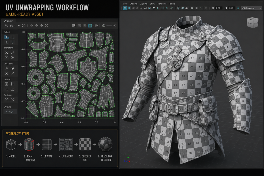
When a 3D model is unwrapped, its surface is cut along designated seam edges and flattened into a two-dimensional representation. The flat sections produced by this cut are called UV islands. Each island represents a portion of the mesh’s surface laid out in 2D texture space. The UV map itself is a square grid, and the canonical region into which islands must be packed for real-time game engine use is the 0–1 UV space: a unit square in which 0,0 is the bottom-left corner and 1,1 is the top-right corner. Most game engines expect all texture UV coordinates to fall within this range for standard diffuse, normal, roughness, and metallic texture maps.
“Editorial illustration created for visual reference purposes. It does not represent a real project, client work, or official software screenshot unless stated otherwise.”
UV seams are the edges along which the mesh is cut to allow flattening. Every seam introduces a discontinuity on the 3D surface: the two edges of the cut are present in the UV map as island boundaries, and texture information does not automatically flow across them. Seams that are visible on the final rendered model—because they fall in a prominent location or because the texturing did not adequately account for them—are the most common symptom of poor UV planning. Seam placement is therefore a design decision, not merely a technical one: it requires the UV artist to anticipate how the texture will be painted, where the camera will be looking, and which edges on the geometry offer natural cut points that the eye will not notice.
The relationship between seams and distortion is the central tension in UV work. Fewer seams means larger, more connected islands, which means fewer visible discontinuities—but also more opportunity for UV distortion, because flattening a curved 3D surface without cutting it inevitably stretches some areas and compresses others. More seams reduce distortion by allowing more controlled flattening, but each additional seam is a potential visible artifact and a boundary that requires adequate padding in the final layout. The correct balance depends on the asset type, the texture type being applied, and the target rendering distance.
Padding is the gap maintained between UV islands within the packed layout. Its purpose is to prevent texture bleeding: at lower mip-map levels, the GPU samples textures at reduced resolution, and if islands are packed too close together, pixel data from one island bleeds into an adjacent one, producing color fringing along seams. Industry standard minimum padding values vary by texture resolution: for a 2048 × 2048 texture, a minimum of 4–8 texels of padding between islands is typically required; for a 4096 × 4096, the same physical gap in texels corresponds to more UV space, so the minimum is often specified as a fixed texel count rather than a UV space percentage. For 3D environment art with complex tiling setups, inadequate island padding is one of the most common sources of visible seaming in lit scenes and in Lumen-based global illumination builds.
Did you know that…?
The letters U and V were chosen for texture coordinate axes specifically because the letters X, Y, and Z were already assigned to three-dimensional spatial coordinates in the same mathematical context. Naming the texture axes U (horizontal) and V (vertical) avoided ambiguity when both coordinate systems appear in the same equation—which they do constantly in the vertex shader code that maps texture samples to mesh surfaces at runtime. The naming convention has been in use since the early days of real-time 3D graphics, predating modern game engines by decades, and it has remained unchanged across every major engine, DCC, and rendering pipeline since.
Texel Density: The Specification That Governs Everything Else
Texel density is the ratio of texture pixels to real-world surface area on a 3D model—typically expressed as pixels per centimeter or pixels per unit. It is the single most important UV specification in production, and it is the one most commonly left unspecified in outsource briefs.
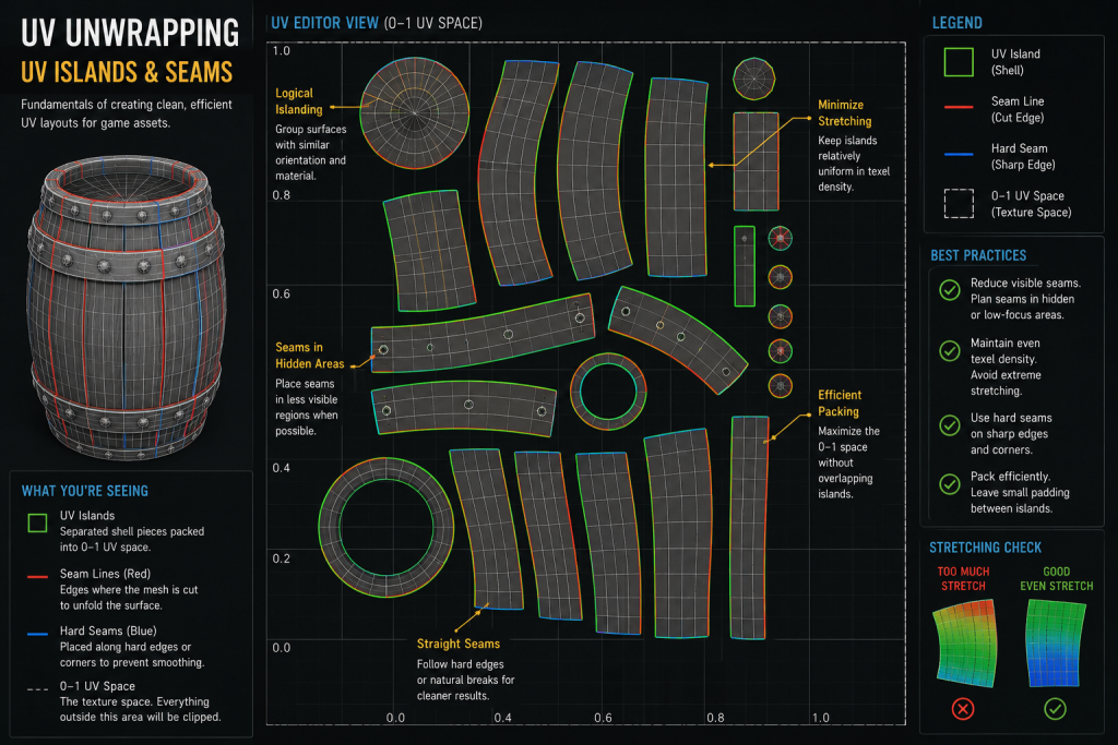
The reason texel density matters is straightforward: if different parts of the same asset—or different assets in the same scene—have inconsistent texel density, the result is visually inconsistent texture detail. A weapon that has 512 px/cm on the body but 128 px/cm on the grip will look like two different assets that were combined. A character whose face receives 4× the texel density of their armor will look like two assets composited together. The inconsistency registers immediately in quality review and is nearly impossible to fix at the texturing stage—it requires returning to the UV layout.
“Editorial illustration created for visual reference purposes. It does not represent a real project, client work, or official software screenshot unless stated otherwise.”
For production work, texel density must be specified before UV work begins, not verified after it is complete. The specification depends on three variables: the asset’s tier (hero, mid, background), the asset’s expected render distance in-engine, and the texture resolution budget allocated to the asset.
Studios typically define texel density targets relative to screen importance and camera distance rather than applying universal numeric standards—the right number varies significantly by project, platform, and rendering pipeline. That said, production decisions are organized around tier-based priorities:
Hero characters and foreground props (assets that appear at close range, occupy significant screen space): highest density tier, typically requiring UDIM multi-tile setups for complex characters to achieve the target density across the full surface.
Mid-tier assets (weapons in third-person contexts, secondary environment props, vehicles seen at medium distance): moderate density, typically achievable within a single 2048 × 2048 or 4096 × 4096 texture set.
Background and tiling assets (architecture, large terrain, repeating modular pieces): lowest density tier on unique surfaces; tiling textures operate differently and are not directly comparable on a per-island basis.
These are not universal constants—different engines, camera systems, and art styles will calibrate differently—but they represent the operational ranges within which most production decisions are made. The important practice is consistency: all islands on a given asset should share the same target density (with documented exceptions for areas that will never be seen at close range, which can legitimately carry lower density to recover UV space for higher-priority surfaces).
For 3D character design work specifically, texel density planning is inseparable from the UDIM decision: a hero character at 2048 × 2048 in a single tile cannot sustain 512 px/cm across the full body without significant compromises on face or hand detail. The UV planning conversation for a hero character should include the texture budget and UDIM tile count before the first island is placed.
Verifying texel density requires a checkermap applied to the mesh in the UV editor or in the DCC application’s viewport. A correctly calibrated checkermap will appear consistent in checker square size across all surfaces of the model. Inconsistency—where some areas show larger checker squares than others—indicates density variation that needs correction. This check should be a mandatory step in every UV review pass, not an optional verification.
Seam Placement and Hard Edge Synchronization
Seam placement is where UV work requires the most deliberate decision-making, and where the interaction between the UV layout and the mesh’s smoothing data is most technically consequential.
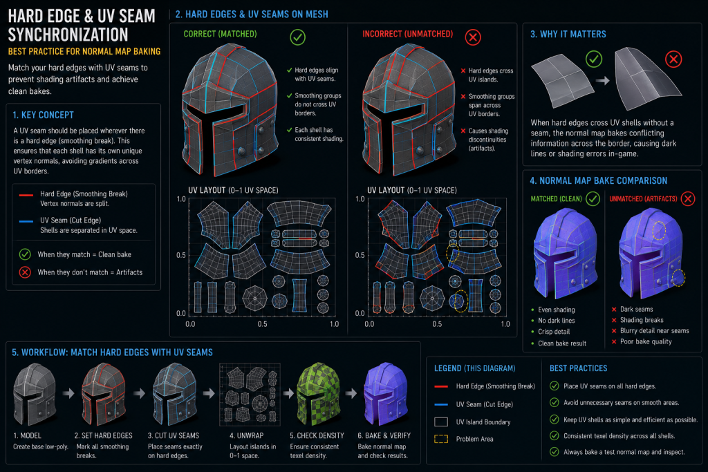
The core production best practice governing seam placement in baked normal map workflows is this: in bake-driven pipelines, UV seams are typically aligned with hard edges, and hard edges commonly coincide with UV seam boundaries. The relationship between hard edges (or smoothing group boundaries, depending on DCC terminology) and UV seams is not universally mandatory—weighted normals, bevel workflows, trimsheet pipelines, and Nanite-based assets may handle this differently—but in standard high-to-low baked workflows it is the default that produces the cleanest results. Understanding why requires a brief explanation of how normal map baking works in terms of vertex data.
Every vertex in a game mesh carries a set of attributes: position, normal direction, UV coordinates. When a hard edge is created, the vertex at that edge junction is split into two vertices with different normal directions—one for each face. When a UV seam is created, the same vertex is split to represent two different positions in UV space. When a hard edge and a UV seam coincide at the same edge, the vertex split happens once, and both requirements are satisfied by a single additional vertex. When a hard edge exists without a corresponding UV seam, or a UV seam exists without a corresponding hard edge, that boundary requires separate vertex attributes—increasing effective vertex count and, in baked workflows, potentially contributing to shading artifacts at the seam boundary in the normal map.
“Editorial illustration created for visual reference purposes. It does not represent a real project, client work, or official software screenshot unless stated otherwise.”
The practical implication is that UV seam placement should be planned in coordination with the smoothing pass, not after it. The workflow that produces the cleanest results is: establish smoothing groups or hard edges based on the mesh’s geometry (any surface angle above approximately 60–90 degrees warrants a hard edge), then place UV seams that match those hard edge boundaries exactly. This allows the bake to project normal data without smoothing conflicts and produces seam boundaries in the UV layout that correspond to natural geometric breaks—where they are least likely to be visible in the final texture.
The Toolbag Baking Tutorial from Marmoset addresses this relationship directly: hard edges at UV seams reduce extreme smoothing on the low poly, which means the resulting bake holds up better at lower mip-map levels and when applied to LOD meshes. This is not a minor optimization—it is a meaningful quality difference that becomes visible at precisely the rendering distances and LOD levels where players actually experience the asset.
Beyond hard edge synchronization, seam placement follows several practical guidelines that apply across asset types:
Place seams at natural geometric boundaries. A seam along the back of a character’s head, under an arm, or along a clothing hem uses the geometry’s own structure to hide the discontinuity. A seam across a smooth forehead or a flat panel has no geometric cover and will require texturing effort to conceal.
Place seams where texture flow is less critical. Areas that will be painted with organic, non-directional textures (skin, worn metal, stone) tolerate seams better than areas with directional detail (wood grain, fabric weave, panel lines). Plan seam placement with the texture artist’s downstream work in mind.
Avoid seams that cross areas subject to deformation. On animated characters, seams that fall across joints or high-deformation areas will shift during animation and may produce visible texture artifacts at the seam boundary under certain deformation states. The detailed polycount AAA pipeline breakdown at Polycount illustrates this directly: straightening islands and aligning them vertically or horizontally along natural edge cuts reduces the anti-aliasing artifacts that appear along diagonal seam boundaries when the texture is sampled at reduced mip levels.
Mirror islands where symmetry permits—with documented exceptions. Mirroring UV islands (placing two symmetric mesh sections on the same UV space) doubles effective texel density at no texture memory cost. The constraint is that any texture detail that needs to differ between the two sides—unique damage, asymmetric wear, identifying markings—cannot be realized on mirrored UVs. The mirroring decision should be documented in the UV spec for the asset, so texture artists know which surfaces are mirrored and plan their painting accordingly.
UDIM, Lightmap UVs, and When Single-Tile Is Not Enough
For most environment props, weapons, and secondary characters, a single 0–1 UV tile at appropriate resolution is the correct approach. The cases where single-tile UV layouts are insufficient fall into two distinct categories: complex hero assets that require more texel density than a single tile can provide, and assets that need to receive baked lighting in a static or semi-static scene context.
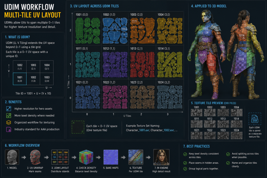
UDIM (U-Dimension) is a multi-tile UV convention originally developed for VFX production that has progressively entered game pipelines as hero asset complexity and texture resolution demands have increased. Instead of confining all UV islands to the 0–1 space, UDIM distributes islands across a numbered grid of tiles: tile 1001 is the standard 0–1 space, tile 1002 covers the 1–2 horizontal range, tile 1011 covers the 0–1 range one unit up, and so on. Each tile corresponds to a separate high-resolution texture file. The result is that a complex hero character can have its face in tile 1001 at high resolution, its body in tiles 1002 and 1003, and its accessories in tile 1011—each receiving the full texel density of an independent 4096 × 4096 texture, without any of them competing for UV space.
“Editorial illustration created for visual reference purposes. It does not represent a real project, client work, or official software screenshot unless stated otherwise.”
The practical decision point for UDIM in game production (as opposed to VFX or cinematic work) is whether the asset is a hero that will be viewed at close range, whether the engine and texturing pipeline support UDIM-based workflows (modern pipelines increasingly do, though implementation varies by engine, renderer, and texture streaming setup), and whether the production budget supports the additional texturing overhead that multiple tiles introduce. UDIM is not appropriate for environment tiling assets, background props, or any asset where a single well-packed tile achieves the required texel density. It is appropriate for primary player characters, photogrammetry-derived hero assets, and cinematically significant props.
Lightmap UVs are a separate UV channel—typically UV channel 1, with the primary texture UV in channel 0, though channel naming conventions vary by engine and DCC—required for assets that will receive pre-baked static lighting in a game engine. It is worth noting that modern UE5 Lumen workflows eliminate the need for precomputed lightmaps entirely, making a dedicated lightmap UV channel unnecessary for fully dynamic lighting setups; however, cross-gen titles, VR targets, and mobile platforms still strictly require unique lightmap UV channels, so the requirement remains common across a wide range of active productions. The requirements for lightmap UVs are fundamentally different from those for texture UVs, and applying the wrong UV philosophy to a lightmap channel is one of the more common sources of light bleeding and shadow seam artifacts in lit environments.
Lightmap UVs must be fully unique—no mirroring, no overlapping islands of any kind—because the lightmap baker assigns unique light and shadow data to every surface position, and overlapping UV coordinates would cause two geometrically different surfaces to share the same light data. This is the opposite of the texture UV optimization that uses mirroring to maximize efficiency.
Lightmap islands must also carry additional padding beyond what texture UVs require. The Unreal Engine documentation on lightmap unwrapping specifies a minimum of four texels of padding between lightmap islands to prevent shadow bleed at standard lightmap resolutions; for production builds at high lightmap resolution, eight to sixteen texels of padding is common. Islands that are tightly packed for texture efficiency will almost always fail the lightmap padding requirement, which is why lightmap UVs are produced as a separate channel rather than reusing the texture UV layout.
The practical pipeline implication is that any static mesh asset intended for use in a lit environment with baked lighting needs two UV channels specified in the art brief: UV channel 0 for textures, and UV channel 1 for lightmaps. Both should be reviewed before the asset is handed off. An asset delivered with only a texture UV channel is incomplete if the production requires baked lighting.
UV as a Deliverable: What Production-Ready UV Packages Require
The production perspective on UV unwrapping differs from the tutorial perspective in one critical way: it is concerned with what is delivered, not just what is done. A 3D artist working on a personal project can make UV decisions that suit their own workflow. An artist delivering into a shared production pipeline must produce UV work that other disciplines can act on without ambiguity.
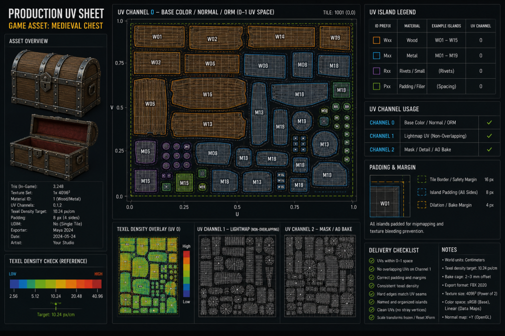
A production-ready UV package for a game asset contains the following:
Clean, distortion-verified UV layout. All islands have been checked with a uniform checkermap at the target texture resolution. Distortion above an acceptable threshold—typically any visible stretching or compression that would manifest as texture artifacts—has been corrected. This check must be performed by the UV artist before submission, not left to the texture team to discover.
Consistent texel density across the asset. All islands are scaled to the project-specified texel density target for the asset’s tier. Documented exceptions (underside faces, fully occluded geometry, areas guaranteed to be outside camera range) are explicitly noted. The target density is documented in the UV metadata or the asset brief.
Seams aligned to hard edges. Every UV seam boundary corresponds to a hard edge or smoothing group break on the mesh. Every hard edge has a corresponding UV seam. The synchronization between smoothing data and UV layout has been verified.
Adequate padding at target texture resolution. Island padding meets the minimum texel gap required for the asset’s target texture resolution, accounting for mip-map level reduction. For assets with lightmap UV requirements, the lightmap channel is delivered as a separate, fully unique UV layout with appropriate padding.
Organized UV space. Islands are oriented consistently—typically with the up-direction of the island corresponding to the positive Y direction of the model—to allow texture artists to paint directional details without geometric re-orientation. Islands are arranged logically in the UV tile, with related parts grouped in proximity to ease texturing and to allow the texture artist to understand which UV island corresponds to which surface without repeatedly checking the 3D mesh.
UV channel documentation. For multi-channel assets, the UV channel assignments are documented: which channel carries texture UVs, which carries lightmap UVs, and any additional channels for special-purpose maps (decal UVs, vertex color blending masks, and so on).
“Editorial illustration created for visual reference purposes. It does not represent a real project, client work, or official software screenshot unless stated otherwise.”
The following matrix provides illustrative production-readiness standards by asset tier. Density values are tier-relative indicators, not universal targets—individual projects calibrate these based on platform, camera system, and rendering pipeline.
| Asset Tier | Typical Texture Resolution | Texel Density Tier | Padding (min) | UDIM | Lightmap UV |
| Hero character | 4K per UDIM tile | High (project-defined) | 8–16 texels | Required for complex assets | Rarely—dynamic lighting common |
| Playable weapon (FPS) | 2K–4K | High | 8 texels | Situational | Rarely |
| Vehicle (playable) | 2K–4K | Medium–High | 8 texels | Situational | Situational |
| Environment hero prop | 2K–4K | Medium | 4–8 texels | No | Often required |
| Modular environment piece | 512–2K | Medium–Low | 4 texels | No | Required |
| Background prop | 512–1K | Low | 4 texels | No | Often atlas |
This matrix reflects commonly observed practices across mid-core and AAA productions and should be treated as a calibration reference, not an absolute standard. Individual projects will specify their own density and resolution budgets based on platform, rendering pipeline, and scope.
At Nasty Rodent, UV layout is not a separate deliverable from the 3D asset—it is part of the asset specification from the first brief pass. Before UV work begins on any character or environment asset, we align with the client on target texel density, texture resolution budget, lightmap requirements, and UDIM scope. The UV layout is reviewed against those specifications before baking begins, not after. This eliminates the most common category of rework in 3D outsourcing: bake failures caused by UV layouts that were not reviewed until the baking stage revealed problems.
If you are building a production pipeline for a mid-core or AAA title and need to align on UV specifications before your 3D art phase begins, our game production case studies show how we approach this across character, environment, and prop pipelines. For studios evaluating a 3D outsource partner for the upcoming production cycle, a 30-minute production alignment call will clarify the specification requirements and confirm whether our workflow fits your pipeline.
Our Approach to UV and 3D Asset Production at Nasty Rodent
UV quality is where production plans either hold or begin to accumulate technical debt. The specification conversation—target texel density, UV tile count, lightmap channel requirements, seam placement conventions—belongs in the brief, not in the bake review. Our approach to 3D character design and environment production starts with those specifications documented and agreed before modeling begins, which means our UV layouts are reviewed against a defined standard rather than intuition.
For studios building or scaling a 3D asset pipeline, our game art blog covers the technical production stack in depth. For studios ready to align on a specific production scope, reach out for a production fit call—we’ll review your asset brief, identify the UV specification gaps, and confirm what a production-ready delivery for your pipeline requires.